The industry trend has been adopt the MT-RJ interface for low data rate (below 1 Gbit/s), multimode applications, and the LC for high data rate (above 1 Gbit/s) applications, both single-mode and multimode (mainly using SX transceivers). Transceiver development has been facilitated by ad hoc industry standards or multisource agreements (MSAs), which govern transceiver package dimensions, electrical interfaces and host board layouts, card bezel design, mechanical specifications (including insertion, extraction, and retention forces), and transceiver labeling. The original MSA for SFF transceivers was supported by 15 companies, including Agilent, IBM, Lucent, Siemens/Infineon, Amp/Tyco, and others. It defined a pin through hole device with two rows of five pins each.

Recently, a second MSA has been approved by the member companies and defines a pluggable transceiver that mates with a surface mountable card receptacle. These small form factor pluggable (SFP) transceivers make it possible to change the optical interface at the last step of card manufacturing, or even in the field, to accommodate different connector interfaces or a mix of SX and LX transceivers. This should make it easier to adjust optical interface characteristics on future system designs, in much the same way that the GBIC transceiver did for the SC Duplex interface (in fact, the SFP is sometimes known as a “Mini-GBIC”). The SFP has 20 signal connections and provides three additional functions in addition to the original 10 SFF signal pins. These new functions include module definition pins that specify a seial ID indicating the type of transceiver function (such as LX vs. SX transceiver), a data rate select function (such as 1 Gbit/s vs. 2 Gbit/s), and a transmitter fault signal.
A metal receptacle, sometimes called a cage or a garage, is surface mounted to the printed circuit board to accept the pluggable transceivers. In addition to providing easy replacement and reconfiguration of the transceiver interface, this offers several other advantages. The transceiver is often the only pin through hole component on a modern card design; the SFP cage allows the elimination of extra manufacturing processing steps and potentially reduces cost. By removing the optical components from the soldering process, the SFP should provide improved reliability of the optics and permits the use of higher soldering temperatures. (This may be important as enviromental regulations require future lead-free solders with higher process temperatures.)

The industry has recently developed enhancements to the SFP MSA, known as SFP Plus (SFP+), which is intended to achieve higher data rates, lower cost, and improved thermal performance. As of this writing, this specification has not been finalized for public release, although SFP+ is applicable to the same application set as SFP, and includes both copper and optical interfaces, it is particularly intended to support high data rate links such as 8.5 and 10.52 Gbit/s Fibre Channel, 10 Gbit/s Ethernet (10.31 Gbit/s links, or 11.1 Gbit/s links using forward error correction, including 10GBASE SR, LR, and LRM), SONET OC-192 (9.95 Gbit/s), and G.709 “OTU-2” (10.7 Gbit/s). The specification is similar to SFP, with a common form factor and optical interface. There is a new electrical interface specification, called SFI, designed to handle higher data rate performance; this is defined in SFP specification 8431. In particular, the jitter budgets are planned to be somewhat tighter for SFI than for a standard SFP interface (though not as restrictive as the XFI interface). We also note that SFP+ has not defined a data rate selection pin, meaning that SFP+ transceivers may be compatible with lower data rates but not necessarily compliant with the older specifications.
A revised SFP+ mechanical specification (sometimes known as “improved pluggable form factor”), including thermal and electromagenetic compatibility, is also available through SFP specification 8432. In particular, SFP+ defines two classes of maximum power dissipation: class A (up to 0.8W) and class B (up to 1.5W). The class B transceivers are intended for DWDM and telecom applications (single-height cage with cooled optics). The SFP+ transceivers are backward compatible with most (but not necessarily all) SFP cages implemented according to the SFF-8074i specification. However, in this case the full benefit of SFP+ improvements in electromagnetic susceptibility and other parameters may not be achievable. At this writing, some important practical questions remain, such as whether the 8G and 10G implementations can be realized with a common transceiver. Although they will use the same optics, 8G Fibre Channel needs to be backward compatible with at least 2 previous generations of the Fibre Channel standard (4G and 2G) using 8B/10B encoding. (10G Fibre Channel uses a different encoding scheme and is therefore not backward compatible with lower data rates.) By contrast, to accommodate the full range of Ethernet standards options including FEC, the 10G transceiver must operate over data rates ranging from 10.3 to 11.1 Gbit/s using 64B/66B encoding. The use of a single electrical receiver design (linear vs. limiting) for 10G remains a design issue, as well as the question of whether clock and data recovery should be more closely integrated into the transceiver.

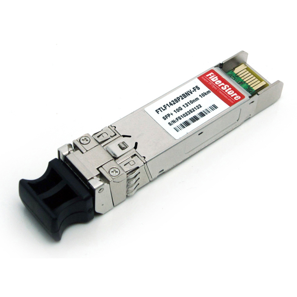
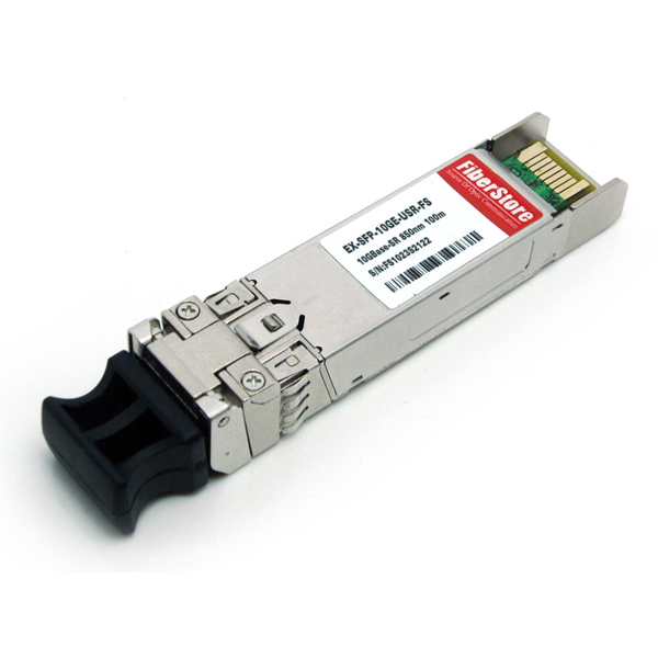
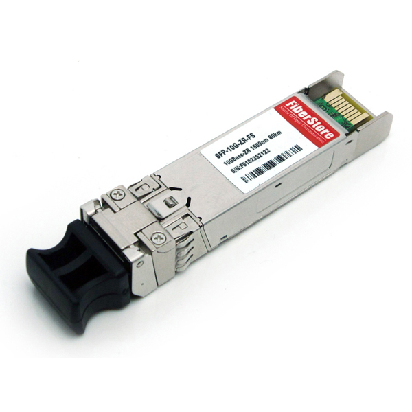
FiberStore is an professional manufacturer & supplier of SFP+ transceivers. We have compatible SFPs for both 8GFC (8G Fibre Channel), 10GFC (10G Fibre Channel), and 10 GbE (10 Gigabit Ethernet) applications. All of our SFP+ transceivers are tested in-house prior to shipping to guarantee that they will arrive in perfect physical and working condition. We provide FTLF1428P2BNV SFP+ for the 8GFC applications, EX-SFP-10GE-USR SFP+ (Juniper compatible) for 10GBASE USR (Ultra Short Reach) applications, and SFP-10G-ZR SFP+ (Cisco compatible) for the 10GBASE ZR applications. For other compatiblebrands, please visit our homepage FiberStore where you can find almost all the fiber optic network solutions!