In optical communication network, signals travel through fibers for very large distances without significant attenuation. However, when the signals need to transmit several hundreds of kilometers, it becomes necessary to amplify the signals during transit. EDFA (erbium doped fiber amplifier), commercialized in the early 1990’s, became a key enabling technology for optical communication networks, and has deployed in the field. It enables the optical signals in an optical fiber to be amplified directly in high bit rate systems beyond Terabits. This article will introduce EDFA from the following aspects.
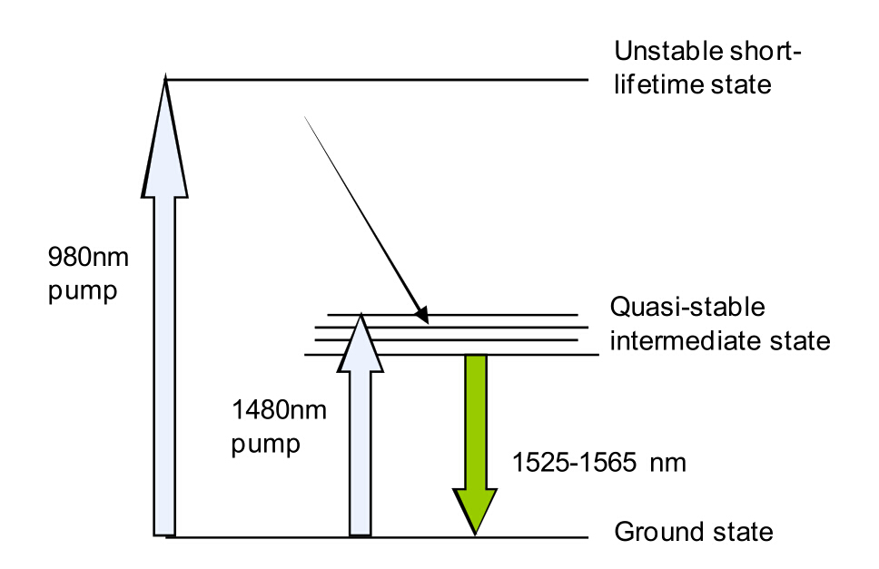
The erbium doped fiber (EDF) is at the heart of EDFA technology. It is a conventional silica fiber doped with erbium. When the erbium is illuminated with light energy at a suitable wavelength (either 980 nm or 1480 nm), it is excited to a long lifetime intermediate state, following which it decays back to the ground state by emitting light within the 1525-1565nm band (see the following picture). If the light energy already exists within the 1525-2565nm band, for example due to a signal channel passing through the EDF, then this stimulates the decay process (so called stimulated emission), resulting in additional light energy. Thus, if a pump wavelength and a signal wavelength are simultaneously propagating through an EDF, energy transfer will occur via the erbium from the pump wavelength to the signal wavelength, resulting in signal amplification.
In its most basic form, the EDFA consists of a length of EDF (typically 10-30m), a pump laser, and a component (often referred to as a WDM) for combining the signal and pump wavelength so that they can propagate simultaneously through the EDF. In principle, EDFA can be designed such that pump energy propagates in the same direction as the signal (forward pumping), the opposite direction to the signal (backward pumping), or both direction together. The pump energy may either by 980nm pump energy, 1480nm pump energy, or a combination of both. Practically, the most common EDFA configuration is the forward pumping configuration using 980nm pump energy, as shown in the picture below. This configuration makes the most efficient use of cost effective, reliable and low power consumption 980nm semiconductor pump laser diodes, thus providing the best overall design with respect to performance and cost trade-offs.
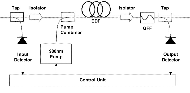
Besides the three basic components described above, this picture also shows additional optical and electronic components used in a basic single stage EDFA. The signal enters the amplifier through the input port, and then passes through a tap which is used to divert a small percentage of the signal power (typically 1-2%) to an input detector. The signal then passes through an isolator, before being combined with pump energy emitted by the 980nm pump laser diode. The combined signal and pump energy propagate along the EDF, where signal amplification occurs, and then the amplified signal exits the EDF and passes through a second isolator. The purpose of the two isolators, which allow light to pass only in a single direction, is to ensure that lasing cannot take place with the EDF. Furthermore, the output isolator also acts as a filter for 980nm light propagating in the forward direction, thus stopping the 980nm light from exiting the amplifier output port.
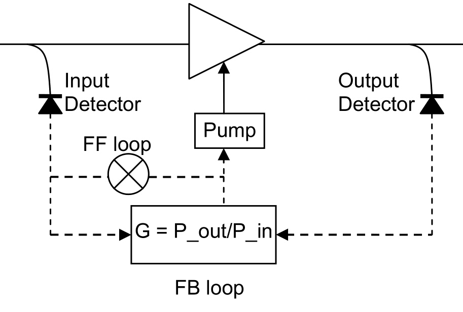
An EDFA is typically operated in one of the two operating modes: AGC (automatic gain control) or APC (automatic power control). In the AGC mode, the amplifier gain is kept constant, whereas in APC mode, the amplifier output power is kept constant. While APC mode is used in some single channel applications, AGC mode is far more common, and is always used in multi-channel WDM applications. The following diagram shows AGC in an EDFA. Information from the input and output detectors is used to calculate the actual gain, which is then compared to the required gain. Based on this comparison, the pump current is then adjusted to change the actual gain towards the required gain. This is a classical feed-back control loop which can be implemented using analogue or digital circuitry. The response time of the control loop is dictated by the response of the EDF to changes in the pump power, which may be quite long (1ms and longer) due to the long lifetime of the Erbium ions’ quasi-stable state.
A brief introduction to the EDFA, one of the most important components in WDM communications, is given in this article. Of the various technologies available for optical amplifiers, EDFA technology is by far the most advanced, and consequently the vast majority of optical amplifiers deployed to date are based on this technology. FS.COM provides various EDFA, including DWDM EDFA, CATV EDFA, etc. Visit www.fs.com for more details.