DWDM is an innovation that enables multiple optical carriers to travel in parallel in a fiber. DWDM devices combine the output from several optical transmitters for transmission across a single fiber. At the receiving end, another DWDM device separates the combined optical signals and passes each channel to an optical receiver. Only one optical fiber is used between DWDM devices (per transmission direction). How DWDM system works, and what components are needed in the DWDM system? Keep reading this article and you will find the answer.
Typically, the components used in a DWDM system include optical transmitters and receivers, DWDM mux/demux, OADM (optical add/drop multiplexers), optical amplifiers and transponders (wavelength converters). Following part will introduce these devices respectively.
Transmitters are described as DWDM components because they provide the source signals which are then multiplexed. The characteristics of optical transmitters used in DWDM systems are highly important to system design. Multiple optical transmitters are used as the light sources in a DWDM system which requires very precise wavelengths of light to operate without interchannel distortion or crosstalk. Several individual lasers are typically used to create the individual channels of a DWDM system. Each laser operates at a slightly different wavelength.
The DWDM Mux (multiplexer) combines multiple wavelengths created by multiple transmitters and operating on different fibers. The output signal of a multiplexer is referred to as a composite signal. At the receiving end, the DeMux (demultiplexer) separates all of the individual wavelengths of the composite signal out to individual fibers. The individual fibers pass the demultiplexed wavelengths to as many optical receivers. Generally, Mux and DeMux components are contained in a single enclosure. Optical Mux/DeMux devices can be passive. Component signals are multiplexed and demultiplexed optically, not electronically, therefore no external power source is required.
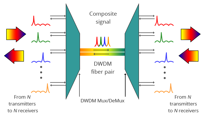
The picture above shows the bidirectional DWDM operation. N light pulses of N different wavelengths carried by N different fibers are combined by a DWDM Mux. The N signals are multiplexed onto a pair of optical fibers. A DWDM demultiplexer receives the composite signal and separates each of the N component signals and passes each to a fiber. The transmit and receive signal arrows represent client-side equipment. This requires the use of a pair of optical fibers—one for transmit and the other for receive.
OADM is often a device found in WDM systems for multiplexing and routing different channels of fiber into or out of a single-mode fiber (SMF). It is created to optically add/drop one or multiple CWDM/DWDM channels into a few fibers, providing the power to add or drop a single wavelength or multi-wavelengths from a fully multiplexed optical signal. This permits intermediate locations between remote sites to gain access to the regular, point-to-point fiber segment linking them. Wavelengths not dropped pass-through the OADM and carry on towards the remote site. Additional selected wavelengths may be added or dropped by successive OADMs if required.
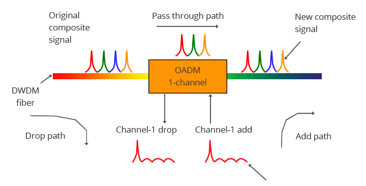
The picture above demonstrates the operation of a one-channel OADM. This OADM is designed to only add or drop optical signals with a particular wavelength. From left to right, an incoming composite signal is broken into two components, drop and pass-through. The OADM drops only the red optical signal stream. The dropped signal stream is passed to the receiver of a client device. The remaining optical signals that pass through the OADM are multiplexed with a new add signal stream. The OADM adds a new red optical signal stream, which operates at the same wavelength as the dropped signal. The new optical signal stream is combined with the pass-through signals to form a new composite signal.
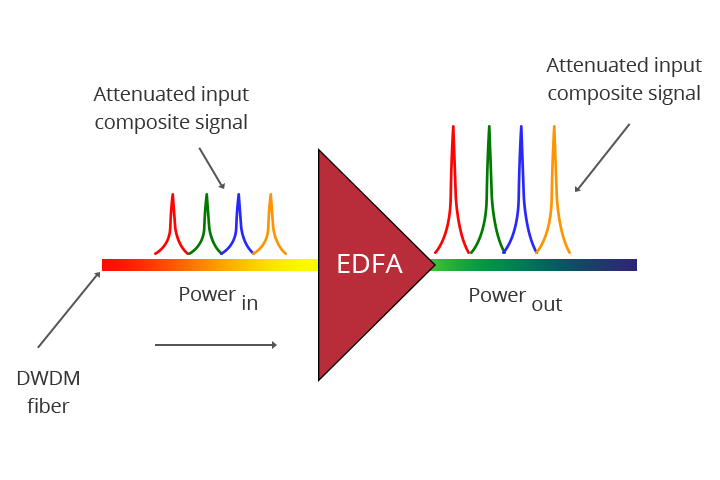
Optical amplifiers boost the amplitude or add gain to optical signals passing on a fiber by directly stimulating the photons of the signal with extra energy. They are “in-fiber” devices. Optical amplifiers amplify optical signals across a broad range of wavelengths, which is very important for DWDM system application.
WDM Transponders convert optical signals from one incoming wavelength to another outgoing wavelength suitable for DWDM applications. Transponders are optical-electrical-optical (O-E-O) wavelength converters. A transponder performs an O-E-O operation to convert wavelengths of light. Within the DWDM system, a transponder converts the client optical signal back to an electrical signal (O-E) and then performs either 2R (reamplify, reshape) or 3R (reamplify, reshape and retime) functions.
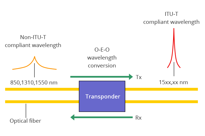
The picture above shows the bi-directional transponder operation. A transponder is located between a client device and a DWDM system. From left to right, the transponder receives an optical bit stream operating at one particular wavelength (1310 nm). The transponder converts the operating wavelength of the incoming bitstream to an ITU-compliant wavelength. It transmits its output into a DWDM system. On the receive side (right to left), the process is reversed. The transponder receives an ITU-compliant bit stream and converts the signals back to the wavelength used by the client device.
This article provides some basic information about the components used in a DWDM system. All of the components compose the integrated DWDM system. And they are indispensable. Hope the information in this article is helpful when building your DWDM system.