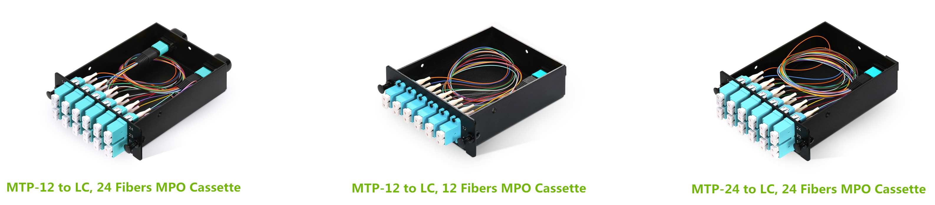
Modular system, which allows for rapid deployment of high density data center infrastructure and improved troubleshooting and reconfiguration during MACs, is more and more popular. MTP cassette, topic of this post, is such a module. It provides a secure transition between MTP and LC or SC discreet connectors, and is used to interconnect MTP backbone cabling with LC or SC patch cables.
MTP fiber optic cassettes are pre-terminated and pre-tested enclosed units. They contain 12-fiber or 24-fiber factory terminated fan-outs inside. MTP modular cassettes serve to “transition” small diameter ribbon cables terminated with MPO connector(s) to the more common LC or SC interface used on the transceiver terminal equipment. Typically, the fan-outs incorporate LC, SC connectors plugged into adapters on the front side of the cassette and MPO connector(s) plugged into MPO adapter(s) mounted at the rear of the cassette. One or more MPO fan-out assemblies can be installed inside the cassette to connect up to two 12-fiber ribbon cables for a total of 24 fibers. Alignment pins are pre-installed in the MPO connector located inside the cassette. These pins precisely align the mating fibers in the MPO connectors at either end of the array cables that plug into the cassettes.
The transition inside a MTP cassette, the connector keying for the MTP cassette module and the corresponding MPO array cables are completely defined for all three connectivity methods listed in the TIA standard as described in the previous post—polarity methods for MTP/MPO system. A common transition, factory installed inside a cassette, is used for all of the three methods. The adapter mounted at the rear of a cassette defines it as either Method A or Method B MTP modular cassette.
Method A MTP cassette makes a “key up to key down” connection between the internal MPO connector and the MPO array cable connector. Method B MTP cassette makes a “key up to key up” connection. The Method B cassette will not allow single-mode angle polish mated pair connections due to the fact that the angles of the mating connectors are not complementary. This prevents a Method B MTP cassette module or adapter from being used in single-mode applications requiring low return losses, a significant limitation with connectivity Method B. The difference between Method A and Method B MTP fiber optic cassette is the orientation of the internal MPO connector with respect to the mating with MPO array cable connector.
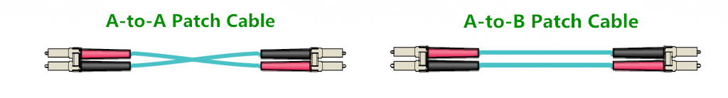
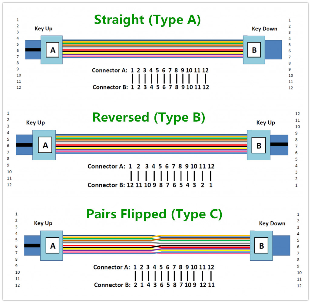
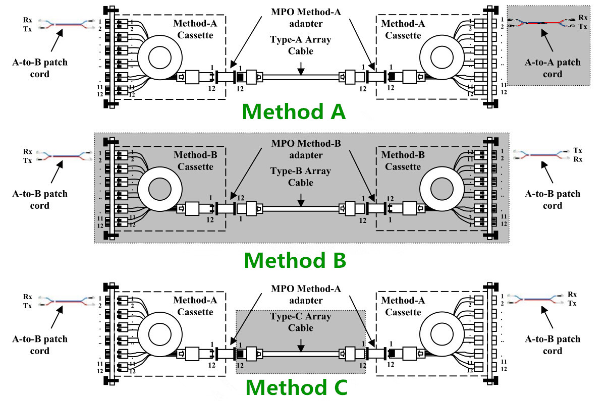
The components deployed for multiple duplex signals include a MTP cassette at each end. Pre-terminated 12-fiber trunk cables connect to the MPO adapter on the back of the two cassettes, and duplex patch cords are used to connect the equipment to the front of the cassettes. There are two types of patch cords “A-to-B” and “A-to-A” and three types of trunk cables “Type A”, “Type B”, “Type C” shown in the following pictures.
The following picture clearly shows the connection rules of every component required for the three connectivity methods.
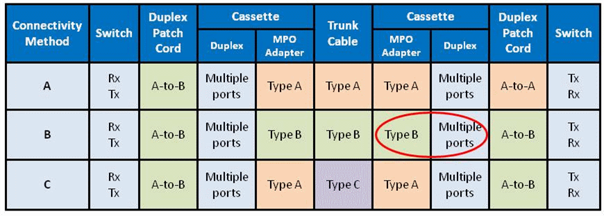
From the picture, we can summarize following connection points:
- Connectivity Method A is the most straight forward but requires a different patch cord at one end.
- Connectivity Method B uses the same patch cord at both ends, but the cassettes (circled in red) must be flipped over at one end so that the fiber that originated in position 1 is mapped to position 12.
- Connectivity Method C is a variant of Method A, but with the cross-over implemented in the trunk cable instead of the patch cord.
Note: No matter which method is selected, there must be a pair-wise flipping (A-to-B polarity swap) that takes place at some point in the link. If the pair-wise flipping does not occur in the cassette then the pair-wise flipping must occur in the duplex patch cord or the MPO trunk cable and/or adapters.
The following picture shows an illustration of the connectivity rules. The numbers shown next to the adapters on the outside of the cassette and the MPO connectors are fiber port designations. The numbers shown in bold next to the adapters on the inside of the cassette are fiber number designations.
In the market, most MTP cassettes are configured in accordance with the TIA Connectivity Method A. Because Method A provides the simplest deployment, works for both single-mode and multimode channels, and easily supports network extensions. In addition, Method A MTP cassettes are also used for Method C connectivity since the key positions are the same in the two methods. Method B configuration is also available on request. However, there is a limitation of Method B that it doesn’t allow use of an angled polished (APC) single-mode connector.
MTP cassette, containing factory controlled and tested MPO/MTP-LC fanouts, delivers high optical performance, rapid and error-free installation and reliable robust operation. Using Type A MTP cassette or Type B MTP cassette is closely related to the other components in the whole system. The best way to maintain correct optical polarity is to choose a standards-based approach and adhere to it throughout an installation. Incorrect connections violating the proper polarity will result in a link failure and possibly damage to critical optoelectronic components. It is best for installers and end-users to buy MTP cassette from a supplier adhering to TIA standards. FS.COM is such a MTP cassette modules manufacturer, who provides both 12 core and 24 core MTP/MPO fiber optic plug-n-play cassettes with low price.
Related Article: MTP Base-8 and Base-12: Correct Using Principles