For many years, data centers have been built in three-tier architecture, comprised of the core, aggregation and access layers. But with the data center consolidation, virtualization, hyper-converged systems springing up, the way data flows is shifting from traditional north-south to east-west inside data center. As the volume of east to west traffic increases, network bottlenecks emerge and application performance decreases if uplinks between layers are oversubscribed. One solution to these problems is a new network architecture—leaf-spine. What is leaf-spine architecture and how to build a fabric with it? This post will explain what leaf-spine is and how to scale on leaf-spine architecture with open networking switches.
Unlike traditional core-aggregation-access layer network, leaf-spine architecture has only two layers. It enables the business to create a large, non-blocking fabric without single point of connections. Leaf switches forming the access layer are no more than one hop away from one another, thus eliminating the need for devices to search for or wait for open connections. These leaf switches are fully meshed to a series of spine switches. As a result, latency improves and bottlenecks are minimized.
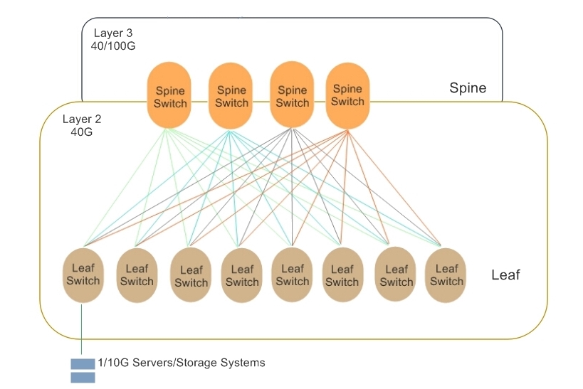
Leaf-spine architectures can be either layer 2 or layer 3, meaning the links between the leaf and spine layer could be either switched or routed. In either link, no connection will be blocked since the spanning-tree protocol (STP) is replaced by other protocols. The following figure shows a simple leaf-spine architecture. The leafs act as the layer 2/3 boundary for the server segments in a fabric. In a layer 2 leaf-spine architecture, the spanning-tree protocol is most often replaced by transparent Interconnection of Lots of Links (Trill) or shortest path bridging (SPB). In a layer 3 leaf-spine architecture, each link is a routed link. Open Shortest Path First is often used to replace STP as the routing protocol to compute paths between leaf and spine switches. Due to its flexibility in reconfiguration and increased number of connections, leaf-spine architecture is very suitable for software defined networking (SDN).
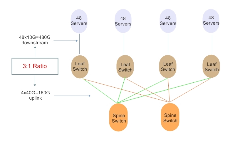
The leaf-spine architecture is much flatter than traditional three layers architecture and more leaf and spine switches can be added in the system. In general, the larger the number of leaf switches needed to uplink all of the physical hosts, the wider the spine needs to be to accommodate them. But the number of the leaf and spine switches is not at random or unlimited. There is an oversubscription rate used to determine if the ratio between leaf and spine layers is acceptable. Usually, an oversubscription ratio of no more than 3:1 is considered acceptable. The figure below uses an example to illustrate how to measure the oversubscription ratio of leaf and spine layers.
Apart from oversubscription, there are some principles which can help decide the switch number in a fabric:
-The uplink port count on the leaf switch determines the maximum number of spine switches.
-The downstream port count on the spine switch determines the maximum number of leaf switches.
-The product of downstream port count on the leaf switch multiplying the leaf switch number equals the server number.
In order to explain how to scale on leaf-spine architecture, here I’ll give examples using 40G and 10G switches. Firstly, we should set our goals. That is to say how many 10G servers we want to have in the fabric, and at which oversubscription ratio. Give that we want to build a leaf-spine fabric comprised of 1200 10G servers at 2.5:1 oversubscription, and we also want to seamlessly expand this fabric to over 5000 10G servers as necessary without increasing the latency or oversubscription.
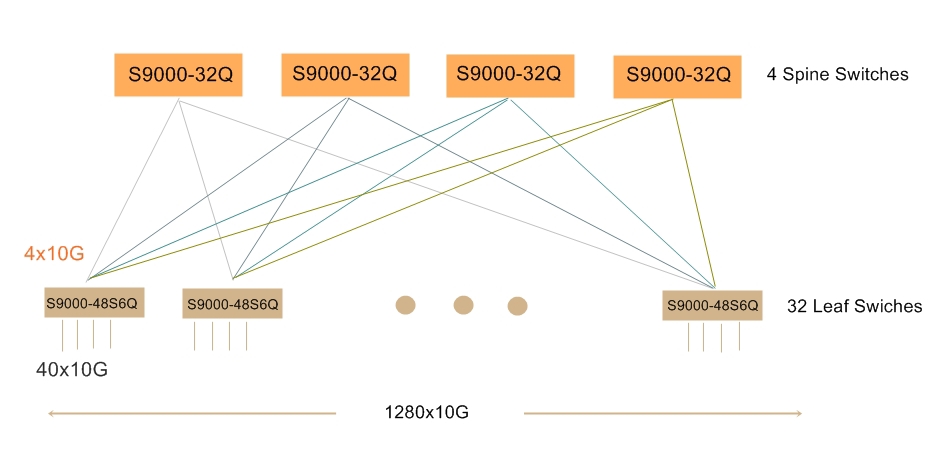
To achieve these goals, I will use FS S9000-32Q ICOS (32*40GbE) as spine switch and FS S9000-48S6Q ICOS (48*10GbE+6*40GbE) as leaf switch in my examples. Both of them are open networking switches compatible with software defined networking via OpenFlow 1.3.11.
In order to build a fabric with 1200 10G servers, we can use 40G QSFP interfaces between the leaf and spine switches. There are 32 40G ports on the spine switch and each leaf switch has 4 ports of 40G connected to the spine. According to the principles of building a leaf-spine fabric, the largest 10G server count I can have is 1280 at 2.5:1 oversubscription.
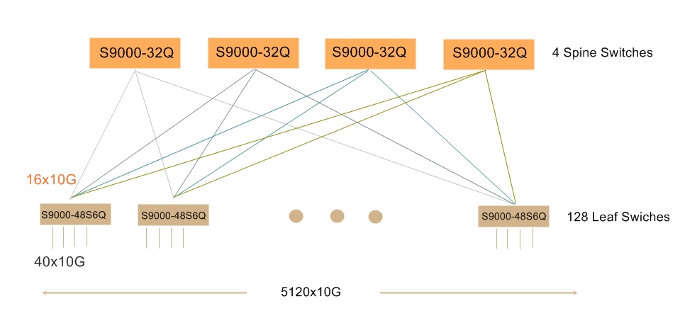
In order to expand this fabric to over 5000 10G servers, we can use optical breakout cables to get 4x10G interfaces on the S9000-32Q spine switches and S9000-48S6Q leaf switches. Then I will have 128 ports of 10G on each spine switch and each of my leaf switches is connected to the spine with 16 ports of 10G. The maximum 10G server count I can have is 5120 at oversubscription of 2.5:1.
This post intends to act as a guide for the basic knowledge about leaf-spine architecture, and explains the use cases of building leaf-spine fabric with 40G and 10G open networking switches. The introduction to leaf-spine topology may not be comprehensive, but it can be helpful for beginners in understanding the structure and principles of leaf-spine fabric quickly.