When migrating from 10G to 40G/100G, it is important to know the MTP polarity and gender. Understanding the MTP polarity can ensure that connections between a transmitter and its receiver across the entire fiber optic system are in a consistent, standards-based manner. In the previous post “Introduction to Polarity Methods for MTP/MPO Systems”, I have introduced the polarity systems for duplex signals. So in this article, I would like to talk about MTP/MPO polarity methods for parallel signals.
As we know, the purpose of array connectivity methods is to create an optical path from the transmit port of one device to the receive port of another device. Different polarity methods to accomplish this goal may be implemented. However, these different methods may not be inter-operable. Any connectivity method requires a specific combination of components to maintain polarity. Figure 1 illustrates the corresponding connectivity methods A, B and C to establish polarity for parallel signals using an MPO transceiver interface with one row of fibers.
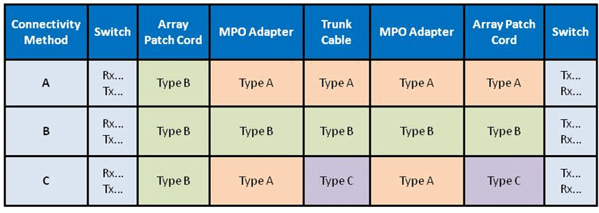
Figure 1: Polarity Methods A, B, C for Parallel Signals
Compared with polarity methods for duplex signals, there are two differences for parallel signals. First, the MTP/MPO cassettes for duplex signals are replaced with MPO-to-MPO adapters for parallel signals. Second, the duplex fiber patch cords for duplex signals are replaced with 12-fiber patch cords for parallel signals. For the details about the polarity differences between duplex signals and parallel signals, you can read “Type A MTP Cassette and Type B MTP Cassette: When and Where to Use?” to know more information about polarity methods for duplex signals. While for polarity methods for parallel signals, keep reading this post for more information.
When connecting arrays for parallel signals, the Type A backbone is connected on each end to a patch panel. On one end of the optical link, a Type A array patch cord is used to connect patch panel ports to their respective parallel transceiver ports. On the other end, a Type B array patch cord is used to connect panel ports to their respective parallel transceiver ports. In each optical path, there shall be only one Type B array patch cord.
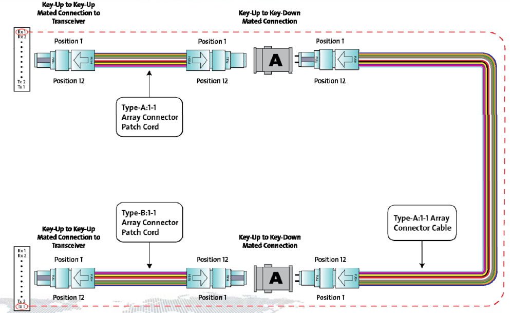
Figure 2: Connectivity Method A for Parallel Signals
When connecting parallel signals, the Type B backbone is connected on each end to a patch panel. Type B array patch cords are then used to connect the patch panel ports to their respective parallel transceiver ports.
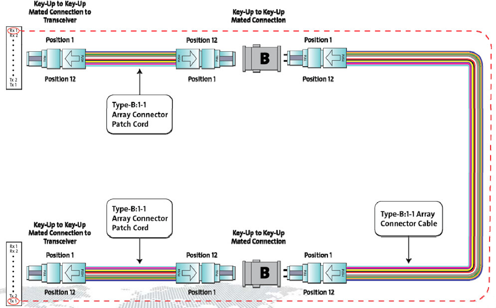
Figure 3: Connectivity Method B for Parallel Signals
Connectivity Method C for parallel signals is similar to connectivity method A. The differences are Type C trunk cable is used instead of Type A, and a Type C cross-over patch cord is required at one end and at the other end, still Type B patch cable used.
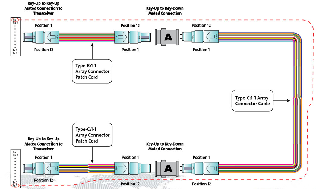
Figure 4: Connectivity Method C for Parallel Signals
An important point to remember is that MPO plugs use alignment pins. MPO transceivers typically have pins (Male) and the patch cords from transceiver to patch panel are typically unpinned (Female) on both ends. Transitions (mounted behind the panel) are typically pinned (Male) on both ends. Cables from rack to rack are typically unpinned (Female) on both ends.
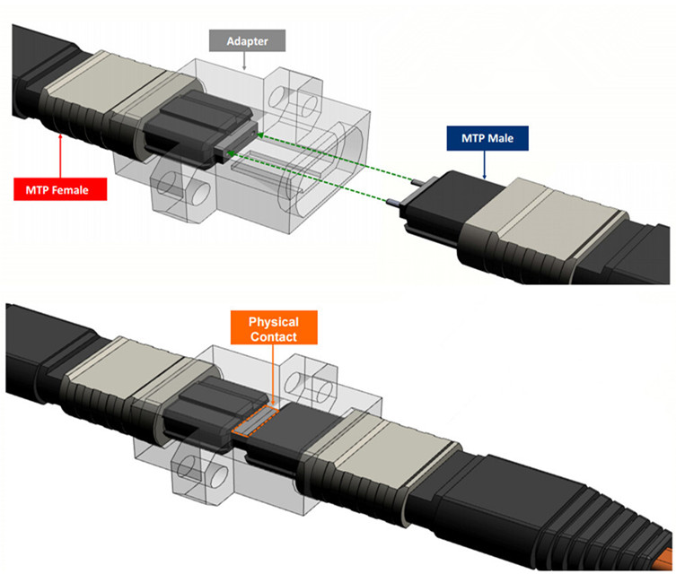
Figure 5: focused on the connection
The physical contact area is the critical joining point in the fiber network. If there is not a clean physical connection, the light path is disrupted and the connection is compromised.
No matter for duplex signals or for parallel signals, there are three types of polarity methods A, B and C. Parallel optical fiber links integrate multiple transmitters in one transmitter module, multiple fibers in fiber array connectors, and multiple receivers in one receiver module. When mating connectors that use alignment pins, it is critical that one plug is pinned and the other plug is unpinned. Typically, the pinned connector is located inside the panel. In other words, the fixed connector is pinned and the connector that is frequently removed and handled in unpinned. Hope the information in this article can help you better understand the MTP/MPO polarity methods for parallel signals.