This article I will introduce three tools in the standards for testing installed fiber. A visible light source or visual fault locator (VFL), an optical loss test set (OLTS), and the optical time domain reflectometer (OTDR).
Visible Light Source
Visible Light Source include incandescent lights and LED and laser light sources. Anything from a flashlight to an LED “keychain” light may be used for continuity and polarity testing. A visual fault locator (VFL) makes the job easier but is simply a very powerful light source. It typically uses a Class 2 laser device – a device that emits light in the visible (red) spectrum. Note that it is very dangerous to look directly into the output, either at the source itself or at the end of a short or long fiber optic cable.
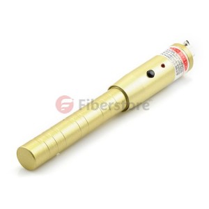
If a fiber optic strand has been broken, it is sometimes possible to see the light emitting through the buffer that surrounds the cable jacket at the location of the break. The most common use for this tool is probably in locating or verifying the correct fiber out of many at a Fibre Optic Patch Panel or other distribution center, and in identifying polarity of a fiber pair.
Optical Loss Test Set (OLTS)
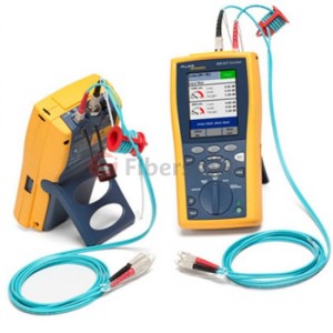
Used for testing power loss over a fiber optic link, the optical loss test set (OLTS) consists of a fiber optic light source and a fiber optic power meter. Light sources usually come in two configurations: 850nm and 1300nm LED sources for testing multimode, and 1310 and 1550 laser sources for testing singlemode. Gigabit and higher data rate systems use vertical cavity surface emitting laser diodes (VCSEL) sources at 850nm because these devices are much faster than LEDs, and much cheaper than the laser sources – usually between half and one fourth the cost. Even though they will be used in the production deployment, VCSEL light sources are not recommended to test and certify the link loss of stalled cabling systems because the launch conditions of these devices are not uniform device to device. For this reason, a test instrument using an LED light source is recommended. The importance of carefully controlling the launch conditions of the test to obtain repeatable and accurate test results has already been mentioned.
OTDR
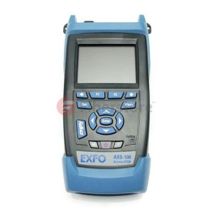
To permit an optical time domain reflectometer (OTDR) to see events at the beginning of a link to be tested properly, a 100 meter launch cable is often used as patch cord 1 to connect the OTDR to the link. The launch cable gives the OTDR’s detector time to recover from the strong reflection at the OTDR connector. The launch cable also permits the OTDR to measure the loss of the first connector to compare to the backscatter after the connector, thus allowing the OTDR to determine the loss across the connector. Without the launch cable, the backscatter before the first connector in the link is lost in the dead zone from the OTDR’s connector. A receiver cable, which is connected to the far end of the link, may also be used to permit the OTDR to measure the loss of the last connector in the link, may also be used to permit the OTDR to measure the loss of the last connector in the link, may also be used to permit the OTDR to measure the loss of the last connector in the link. To keep the physical size of this cable small, it is often constructed with unjacketed fiber in a spool that is spliced to jacketed ends.
 Finally there are some helps for you, above all the products i have mentioned all can be found in the Fiberstore, Fiberstore is a famous Supplier, including all kinds of optical fiber products, and the good news is that the patch panels are all on hot sales, including SC, FC, LC patch panel and some ports patch panel, such as 6, 8, 12, 24 port fiber patch panel. If you need some, welcome to contact me.