Due to the increasing number of connected devices in use and their need for fast-based data processing, data centers are under pressure of transmitting data more quickly and efficiently. In order to keep pace with the rapid bandwidth increases, the applications standards organizations have been busy updating the recommended guidelines. Some intermediate speeds like 25 gigabit Ethernet are being developed to fit the gap between 10G, 40G, 100G and 400G. This post will discuss the benefits of 25G data rate and the connectivity solutions for 100GBASE-SR4 optical transceiver and 25GBASE-SR optical transceiver.
According to the IEEE standards, 25G Ethernet is now defined for both single-lane and four-lane versions of 25G.
The first benefit brought by 25G is that by offering the single-lane 25Gb/s variant, 25G allows for the optimization of bandwidth available from switch-fabric design. Before this standard arrives, the only options were one lane at 10Gb/s, four-lanes 10Gb/s for 40G, or four-lane 25Gb/s for 100G. This new standard adds an important intermediary step of a single lane of 25G. With the implementation of 25G data rate, one can choose to use four different links at 25G to connect to a switch, rather than limited to using all four lanes of a QSFP port from one individual devices to another to achieve 100G throughput.
The second advantage is it takes the existing form factors, such as SFP28 and QSFP28, and allows for a breakout connection that is configurable as either 25G per lane or the full 100G without changing the port on the front of switches.
The last benefit is that it can take existing optical plants (depending on what was installed) and increase the bandwidth by 2.5x compared with 10Gb/s without changing the physical infrastructure.
In this part, the connectivity solutions for 100G and 25G optics will be introduced. As mentioned before the standards for these optical transceivers are 100GBASE-SR4 and 25GBASE-SR.
When directly connecting one 100G QSFP28 transceiver with four 25G SFP28 transceivers, an 8 fibers MTP to 4 x LC harness cable is able to do the task. This solution is suitable when the connected optics are arranged in short distances, like in the same rack/cabinet.
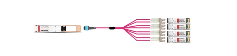
Figure 1: direct connectivity for 100G and 25G via MTP-8 harness cable.
For the first interconnect solution, it allows for flexible patching on both the 100G end and the 25G end. On the QSFP28 end, patching is done by using polarity B female MTP to male MTP trunk cable. On the SFP28 end, patching is accomplished by using MTP modular cassette and LC duplex cables. The equipment used in this solution is shown in the table below.
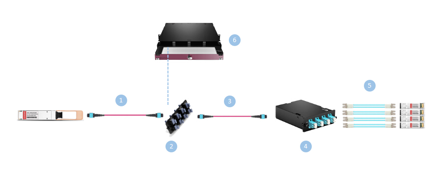
Figure 2: interconnect for 100G and 25G via MTP adapter panel and MTP-8 breakout cassette.
Table 1: items used in solution of figure 2.
| Item | Description |
| 1 | MTP Female to MTP Male 8 Fibers OM4 50/125 Trunk Cable, Polarity B |
| 2 | MTP/MPO Fiber Adapter Panel with 8 MTP, Key up/Key up |
| 3 | MTP Female to MTP Female 8 Fibers OM4 50/125 Trunk Cable, Polarity B |
| 4 | MTP-8 (male) to LC UPC Duplex OM4 8 Fibers MTP/MPO Breakout Cassette |
| 5 | LC UPC to LC UPC Duplex OM4 Elite BIF Fiber Patch Cable, 0.15dB IL |
| 6 | 1RU Rack Mount HD Fiber Enclosure Unloaded |
The second interconnect solution eliminates the insertion loss of the MTP connector pair in the previous solution and thus reduces the amount of system attenuation. But it has defects caused by the limited tail length of the breakout module. So this solution works best when the connected QSFP28 and SFP28 optics are within the same row.
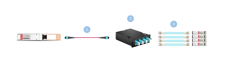
Figure 3: interconnect for 100G and 25G via MTP trunk cable and MTP-8 breakout cassette.
Table 2: items used in solution of figure 3.
| Item | Description |
| 1 | MTP Female to MTP Female 8 Fibers OM4 50/125 Multimode Trunk Cable, Polarity B |
| 2 | MTP-8 (male) to LC UPC Duplex OM4 8 Fibers MTP/MPO Breakout Cassette |
| 3 | LC UPC to LC UPC Duplex OM4 Elite BIF Fiber Patch Cable, 0.15dB IL |
The last interconnect solution is illustrated in the following figure. It has shortcoming that the flexibility on the SFP28 end is lost. This is because the transceiver ports need to be located in the same chassis since the LC leg lengths of the harness cable are the same. But this solution provides an easy path for both 10/40G and 25/100G upgrade. From the SFP28 ports, an 8 fibers MTP harness is used, and then an 8 fibers MTP patch cord is used from the adapter panel to the QSFP28 port. Thus it allows a mix and match upgrade patch without having to change out the patch panels.
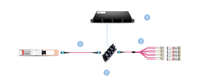
Figure 4: interconnect for 100G and 25G via MTP trunk cable and MTP-8 harness cable.
Table 3: items used in solution of figure 4.
| Item | Description |
| 1 | MTP Female to MTP Male 8 Fibers OM4 50/125 Multimode Trunk Cable, Polarity B |
| 2 | MTP/MPO Fiber Adapter Panel with 8 MTP, Key up/Key up |
| 3 | MTP Female to 4 LC UPC Duplex 8 Fibers OM4 50/125 Harness Cable, Polarity B |
| 3 | 1RU Rack Mount Fiber Enclosure Unloaded |
After reading this post you may find that the upgrade from 25G to 100G is similar to that for 10G to 40G. And in these connectivity solutions, by using MTP-8 equipment, 25G to 100G direct and interconnect links are accomplished with high cost effectiveness. Some solutions are also of much flexibility and allows for future speed increases. The devices used in the solutions are recorded in the tables respectively, and if you have any needs, you can see more details about them by clicking on the names.