Background
Over the past decades, fiber optic technology has revolutionized the telecommunications industry, enabling high-capacity, long-distance communications and networking at staggeringly low costs. Fiber optics have also played important roles in numerous other applications: They have been used to deliver light for precision marking and cutting; as a practical, high-power, high-coherence laser source; for imaging systems; and as a means for providing illumination in inaccessible places—not to mention for artificial Christmas trees of questionable taste (which have admittedly appeared in our lab during the festive season).
Even before fiber optics made it big in the telecom industry, the fiber optic technology was showing promise in the fields of industrial and environmental sensing. Decades of research are now being translated into safe, precise fiber-based measuring instruments, including gyroscopes, temperature probes, hydrophones and chemical monitors. Indeed, fiber optic sensors are finding applications everywhere from railways, tunnels and bridges to industrial ovens and waste-disposal systems.

Fiber sensing—the use of fiber optics for industrial and environmental sensing applications—is another exciting growth area for this versatile technology. It is, for example, the only discipline within the broader field of sensing that has its own energetic series of conferences. At these meetings, researchers have described potential techniques for measuring everything from blood sugar levels to gravitational waves. Some ideas have made the leap from the laboratory into the highly competitive market of sensor technology. The use of fiber optics for sensing applications actually predates its applications in communications networks. It started with the development, in the mid-1960s, of the “Fotonic” sensor, a bundle-based device that measures distance and displacement, particularly in the machine tool industry. Although the Fotonic was an imperfect technology with a brief career, the idea behind the sensor captured the imagination of the research community.
Introduction of Fiber Optic Sensors
Mechanism
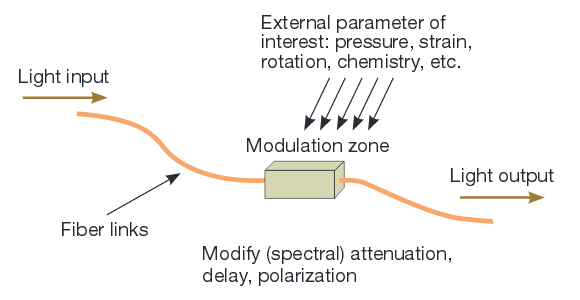
The basic mechanism is simple (shown in the figure below): Feed light into an optical fiber; arrange for the light to be modulated based on its interaction with the parameter of interest; and then transmit the modulated light back to a monitoring point. There are various ways to go about each step—in particular, the approach used to modulate the light—but this is the essence of the technology.
Advantages
Fiber optic sensors offer many advantages over other sensing techniques. Perhaps most important, these sensors are immune to electromagnetic pickup and can be accessed through the fiber links for very long distances—sometimes extending to tens of kilometers. The fibers are also intrinsically safe in hazardous environments. In addition, they are chemically passive, have small physical dimensions, and are mechanically compatible with a host of operational environments.
Drawbacks
Inevitably, these sensors have drawbacks as well. Data interpretation is difficult with certain applications, for example, and developing user confidence and regulatory acceptance can be a lengthy process. Unlike with high-bandwidth communications, where fiber-optics is the undisputed lead technology, there are numerous other options available in the field of sensing; fiber-optics is rarely the obvious choice—although it can be a very good one.
Function & Applications
Fiber optic sensors are particularly versatile when based on environmentally sensitive interferometers that use a fiber architecture or when monitoring coloror wavelength-sensitive behavior. The former category includes interferometers for measuring dynamic pressure fields (hydrophones and geophones, for example) and the Sagnac interferometer for rotation; the latter encompasses almost everything spectroscopic, including sensors based on interactions with intermediate reagents (for example, an acid/alkali indicator)—often referred to as optrodes—and direct spectroscopic measurements in gases, liquids and solids. This category also includes environmentally sensitive spectral filters, of which the Fiber Bragg Grating (FBG) is by far the most well known.
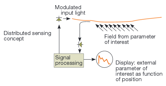
A very important—but far less obvious—modulation mechanism incorporates inelastic interactions among the incident light, the material of the fiber itself and the environment surrounding the fiber. These interactions, of which Raman and Brillouin scattering are the most significant, produce characteristic nonlinear changes to the spectra of the light propagating along the fiber in both forward and, crucially, backward directions. Indeed, the ability of optical fibers to produce predictable backscattering opens up new prospects for sensing applications. Sensor systems that can measure the time delay between the launch and return of backscattered radiation can be used to probe the environment along the fiber. These so-called distributed sensor techniques are unique to fiber optic technology.
Distributed sensors facilitate measurements of strain and temperature over very long interaction lengths—to many tens of kilometers. Moreover, depending on the temporal processing modulation on the launched light, the strain or temperature field can be resolved with more than adequate precision over gauge lengths on the order of 1 meter, or in some systems even less. Similarly, fiber optic sensors can be readily configured into multiplexed configurations of arrays of point measurement devices. Each device requires only one optical source to energize the network. This ability to multiplex typically up to a few hundred interrogation points is another defining feature of fiber optic sensors.
Fiber Optic Sensors in Practice
The field of sensing is rife with idiosyncratic technologies that address specialist applications, and fiber sensing is no exception. Even when the same type of technology can be used to address a range of needs, individual devices can vary greatly depending on the specific application and its requirements of accuracy, stability, resolution, manufacturing volume and a host of other interdependent parameters.
Distributed Temperature Sensing
Well over decades ago, the Raman Distributed Temperature Sensing (DTS) probe emerged as a prototype system based on fiber sensing (the DTS concept is shown in the figure below). This probe is capable of measuring temperature profiles with a 1℃ accuracy and repeatability over gauge lengths of 1 meter or so and total interrogation lengths of tens of kilometers in measurement times on the order of a minute. The DTS is a powerful tool for measuring temperature changes in tunnels and pipe lines. Many systems are now installed in underground railways, highway tunnels and large industrial ovens. Other systems have been placed in large electrical machinery, which may be prone to overheating under fault conditions.
The principal benefit of the DTS is that this technology is equivalent to many thousands of thermocouples, spaced at 1-m intervals along an extended measurement structure. With other temperature sensing systems, electrical wiring, networking and powering can be impractical, especially in areas where intrinsic safety might be important. However, with DTS, users can simply roll out the fiber and attach it in a safe place. Multiplexed networks are also potentially very important, although they have yet to establish the commercial niche enjoyed by the DTS. Networks of FBGs written in a single fiber length have been extensively evaluated as arrays of strain and/or temperature sensors for load and condition monitoring, particularly in carbon fiber composite structures. Often dubbed as “smart structures”, these arrays of sensors facilitate the gathering of operational data from structures such as aircraft and bridges.
In principle, these data can be used to determine the integrity of the structure of interest. But in practice, this remains fraught with difficulty. Certainly researchers and engineers can gather extensive data, but how to interpret these data is the subject of considerable debate. The aim is to denote reliable indicators of structural integrity. However, developing user confidence and regulatory acceptance is a protracted process. Environmental monitoring is yet another potential application for multiplexed systems. The generation of methane gas in a landfill site is an important indicator of both the safety of the site and the progress of the anaerobic decomposition processes that are taking place within it. A measurement system that monitors methane gas concentrations over a site with dimensions on the order of 10 km offers the benefit of continuous assessment and consequently improved operation, especially when the methane—an extremely active greenhouse gas—can be used to generate several megawatts of electrical power.
Fiber optics systems that target this application show enormous promise; they are based on small absorption cells interrogated using single-mode fiber links. As environmental regulations become tighter, such systems offer a potentially definitive technology for monitoring waste disposal operations. Using this approach, multiplexed systems that address more than 200 sensors from a single laser source are feasible. However, rather like the FBG strain sensor arrays, the question of what to do with all the data that these systems acquire is perplexing. In addition, incorporating this system potential into environmental legislation and regulatory standards is a time-consuming process.
Fiber Optic Gyroscope
There are areas in which fiber optic sensors have begun to establish themselves as the natural choice. They are extremely competitive as hydrophones and geophones, again in multiplexed arrays. As an individual sensor element, the fiber optic gyroscope is arguably the most successful. (A fiber optic gyroscope is shown in the figure below.)

Gyroscopes measure rotation in inertial space; they are essential instruments in navigation and positioning systems and in the stabilization equipment that is used extensively in aircraft and ships. The fiber optic gyroscope is based on a fiber optic realization of the Sagnac interferometer—which was first demonstrated almost a century ago. The idea behind the Sagnac interferometer is simple. Light is launched from a beam splitter in two directions around a loop and the loop is rotated. While the light is in the loop en route back to the beam splitter, the light rotating in the same direction as the beam splitter has a little farther to go than the light rotating against the direction of the beam splitter. Consequently, there is a small time delay between the light beams rotating in the two directions on their arrival back at the beam splitter. This time delay can be measured interferometrically as an optical phase.
The realization of this concept in fiber optic form requires some elegant optics and careful engineering. About a decade of effort has yielded highly precise rotational measurement instruments with very high reliability. That dependability lies in the fact that, unlike mechanical gyroscopes (or even the ring laser system, which is also based on the Sagnac effect), fiber optic gyroscopes have no mechanical moving parts. In addition, the scale factor of the fiber optic gyroscope is independent of mechanical acceleration, in contrast to the more established mechanical spinning wheel technology. Furthermore, the fiber optic gyroscope can be configured in a host of different versions addressing diverse needs in terms of accuracy, lifetime and environmental tolerance. Several hundred thousand fiber optic gyroscopes are manufactured and sold per year.
Another successful fiber optic sensor that has found extensive application in civil engineering is the SOFO (a French acronym for Monitoring Structures using Optical Fibers) system. This white-light fiber Michelson interferometer acts as a precision extensometer over gauge lengths up to a few tens of meters, with long-term stability and a precision mechanical readout measured in microns.
Stimulated Brillouin scattering has been used for distributed strain measurement, most notably on installed fiber optic communication cables in earthquake-prone areas. In biomedicine, successful in vivo systems—to evaluate the gastric juices in humans, for example—have become established as useful diagnostic tools. There are many others.
The Future of Fiber Optic Sensors
Fiber optic sensors continue to fascinate. As in other areas of photonics, researchers are excited about the prospect of molding new technologies into the sensing and instrumentation context. Photonic crystals and photonic crystal fibers look interesting—although researchers have barely begun to figure out how to interpret these prospects into the somewhat orthogonal sensor-system environment. High-power lasers based on fiber optic technology enable especially innovative nonlinear characterization of materials. The fiber optic taper will no doubt re-emerge as a probe to examine structures on the microscopic, or even nanoscopic, scale.
Innovations in computing and the availability of extended data-handling capability will also help to improve our ability to interpret data from large arrays of similar sensors and lead to useful combinations of complementary sensors. There are also opportunities with optical micro-electromechanical systems, though these have yet to make their mark as fiber-based sensor technologies. Exploitation of fiber optic sensor technology will continue to expand, slowly but steadily. In parallel, the research community will keep investigating new tools and seeking out opportunities to apply them.